KYOCERA DF-470 Installation Guide
Browse online or download Installation Guide for Trays & feeders KYOCERA DF-470. KYOCERA DF-470 User Manual
- Page / 76
- Table of contents
- BOOKMARKS
- FS-6025MFP/ FS-6030MFP 1
- LE 01 OverviewLE 01 Overview 4
- Touch panel 7
- Installation 8
- (continuation) 9
- Duplex unit 15
- Developing 17
- Fuser unit 19
- Eject unit 20
- Scanner unit 22
- Miscellaneous 24
- Switch and senso 27
- Maintenance 28
- Maintenance Kits 28
- Cover disassembling 29
- Firmware upgrade 32
- Leading edge 34
- System menu 36
- Maintenance mode 37
- Paper jam detection 43
- User Login Administration 44
- Access to the Command Center 46
- Design o 47
- Helpful hints 49
- Change password 52
- Network safety 55
- Authentication models 58
- Authentication 58
- • Scan to email 65
- • Scan to SMB 65
- • Scan to FTP 65
- Blank Page 75
- IF YOU HAVE ANY QUESTIONS 76
- CONTACT US! 76
Summary of Contents
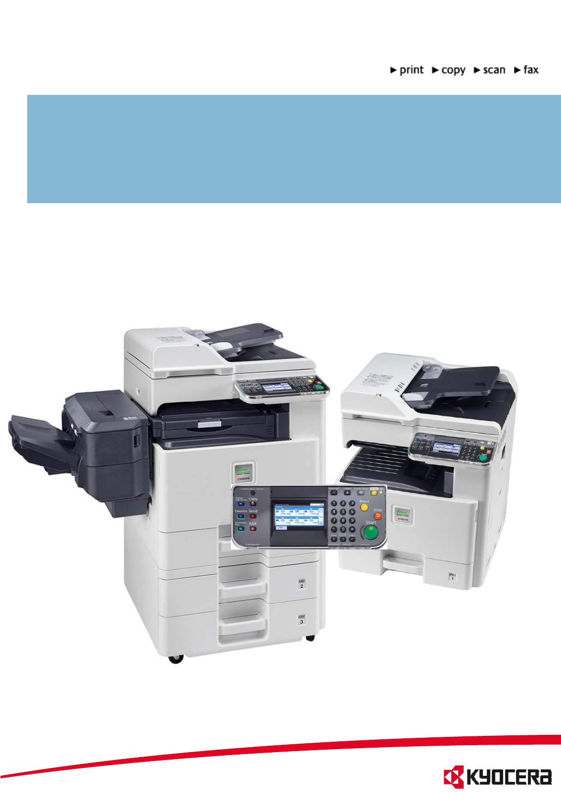
B/W-MULTIFUNCTIONAL SYSTEM FOR PAPERSIZE UP TO A3FS-6025MFP/ FS-6030MFP
LE 03 ConstructionLE 03 Construction1. Cassette2. Cassette paper feed section3 MP tray paper feed section3. MP tray paper feed section4. Conveying sec
LE 03 ConstructionLE 03 ConstructionPaper feederBy inserting the cassette the liftmotor (LM) starts.It stops by swichting the LIFTFULL sensor.The auto
LE 03 ConstructionLE 03 ConstructionPapercassetteThe paper cassette automatically detect’sthe paper size by PWSW (width) and PLSW (lenght) switches.Pa
LE 03 ConstructionLE 03 ConstructionPaper feed unitp1. Main Motor2. Paper feed clutch3. Regist clutch4. Duplex clutch5Lift motor5.Lift motor55
LE 03 ConstructionLE 03 ConstructionPaper feed unitThe registration roller has a big diameter to prevent paper curl.pPaper loopCassetteRegist& fee
LE 03 ConstructionLE 03 ConstructionDuplex unitThe Job Separator is used to turn around the paper for duplex printing Therefore it’s betterpaper for d
LE 03 ConstructionLE 03 ConstructionDitThe main parts of the drum unit are:• a-Si drum• Charge roller• Cleaning blade and cleaning rollerDrum unitgg•
LE 03 ConstructionLE 03 ConstructionDevelopingunitMono componentsystem300.000pagesDCVoltageVdc 160VACVoltageVpp 1.80kVDevelopingunitNoToner
LE 03 ConstructionLE 03 ConstructionTransfer and SeparationThe transfer of the toner from the drum to the paper happens by the transfer unit.The sepa
LE 03 ConstructionLE 03 ConstructionThe Fuser unit is only available as one unit. The most important specifications are:Fuser unit1 contact Thermostat
MdlTPM6030MFPModule name: TPM-6030MFPKYOCERA ACADEMYAuthor: U. KunterCreation: 03/11Version: 1.0Note:All the contents of this document have been care
LE 03 ConstructionLE 03 ConstructionEject unitEject unitThe Eject unit has 2 trays. The main tray is the inner tray. The secondary tray is the Job Sep
LE 03 ConstructionLE 03 ConstructionLaser Scanner UnitLaser Scanner UnitDespite the speed of more than 39600 rpm the LSU is quiet, because the polygon
LE 03 ConstructionLE 03 ConstructionScanner unitThe scanner has something new. For example the new LED bracket with 28 LED‘s. For an equal light sprea
Scanner unitLE 03 ConstructionLE 03 ConstructionThe Image Scanner Unit is fixed with 4 screws. After replacing the unit the number on the lens must al
LE 03 ConstructionLE 03 ConstructionMiscellaneousBehindthe f rontinner coveryou willfindthe Humidity Sensor(1),Interlockswitch(2)and DKconne
LE 03 ConstructionLE 03 ConstructionBelow the Inner Tray and the fan duct you will find more components.1. LVU sub PWB2. AC cut PWB (Relay PWB)3LVU ma
LE 03 ConstructionLE 03 ConstructionPWB’sPWB s1. Main PWB (MPWB)2. Engine PWB (EPWB)3. High Voltage PWB (HVPWB)4. Power source PWB (PSPWB)5. Power sou
LE 03 ConstructionLE 03 ConstructionSwitch and sensor1. Home position sensor (HPS)2. Original detection switch (ODSW)3. Original size sensor (OSS)4. F
LE 04 MaintenanceLE 04 MaintenanceMaintenance KitsMaintenance KitsFor maintenance there is no tool kit necessary. After assembling the units you have
LE 04 Maintenance LE 04 Maintenance Cover disassemblingMost of the cover parts are fixed without screws. It’s important to look at the hook points and
Note for studentsNote for studentsThis training manual contains information, topics for discussion, exercisesconcerning your course, and is organized
LE 04 MaintenanceLE 04 MaintenanceTo disassemble the front upper cover,remove the cassette, open the front cover dllth i ht idCover disassemblingand o
LE 04 Maintenance LE 04 Maintenance Remove the inner rear tray cover by pulling it out on the left side first.Cover disassemblingRemove one screw and
LE 04 MaintenanceLE 04 MaintenanceThe Firmware includes several different files and the data size is approximately 105MB.Please use always the compl
LE 04 Maintenance LE 04 Maintenance U425 automatically calibration of the scannerU-425, automatically calibration of the scannerAfter repairing or rep
LE 04 MaintenanceLE 04 MaintenanceU-425, automatically calibration of the scanner1. Place the calibration chart on the contact glass. 2. Close the doc
LE 04 Maintenance LE 04 Maintenance System settingsActivityRecommendationEntry in the service settings (Adjustment/Maintenance).• If the copier or pri
System menuLE 04 Maintenance LE 04 Maintenance System menuAuto Color CorrectionThis setting allows you to adjust the detection level used by the machi
Maintenance modeLE 04 MaintenanceLE 04 MaintenanceMaintenance modeActivity Enter the maintenance mode.Recommendation • For setting the U-Parameter• To
Maintenance modeLE 04 MaintenanceLE 04 MaintenanceSection Item No. Content of maintenance item Default setting* General U000Outputting an own-status r
Maintenance modeLE 04 MaintenanceLE 04 MaintenanceSection Item No. Content of maintenance item Default setting*High voltage U100Setting the main high
LE 01 OverviewLE 01 OverviewAtalookDF-470500 Sheet FinisherAta lookAK-470 Bridge unitFS-6030MFPFS-6025MFP FS-6020/ B (without Document Processor)FS60
Maintenance modeLE 04 MaintenanceLE 04 MaintenanceSection Item No. Content of maintenance item Default setting*ModesettingU326Setting the black line c
LE 04 MaintenanceLE 04 MaintenanceImageadjustmentprocedureImage adjustmentprocedureStep Adjustment Image Setting maintenance mode Note/ remark1 Print
ImageprocessingLE 04 MaintenanceLE 04 MaintenanceImage processingStep Adjustment Image Setting maintenance mode Note/ remark9 Adjustment of parallelis
LE 04 MaintenanceLE 04 MaintenancePaper jam detectionPaper jamThe code of the paper jam has 4 digits.So the description of the paper jam position is m
LE 04 MaintenanceLE 04 MaintenanceUser Login AdministrationA new feature of the configuration menu is My Panel.If the User Login Administration is ena
LE 05 Command CenterLE 05 Command CenterCttContents:• Access• Design• Helpful hints• Safety concept• Passwords• Blocking the Operation PanelBlocking i
LE 05 Command CenterLE 05 Command CenterAccess to the Command CenterAccess to the Command Center is available via a web browser (e.g. internet Explore
LE 05 Command CenterLE 05 Command CenterDesign ofthe Command CenterThe Command Center is divided into the following areas:1. Main MenuAccess to the m
LE 05 Comman CenterLE 05 Comman CenterLE 05 Command CenterLE 05 Command CenterStyle of presentation in this manualEach function of the Command Center
LE 05 Command CenterLE 05 Command CenterLE 05 Command CenterLE 05 Command CenterHelpful hintsEntriesAll entries in the Command Center have to be confi
LE 01 OverviewLE 01 OverviewOptions indetailOptions in detailDPOriginal size: A5 –A3Paper weight: Simplex: 45 – 160 g/m²Duplex: 50 – 120 g/m²max.5
SafetyConceptLE 05 Command CenterLE 05 Command CenterLE 05 Command CenterLE 05 Command CenterSafetyConceptRequirements MeasureThe device's system
LE 05 Command CenterLE 05 Command CenterDevicesafetyLE 05 Command CenterLE 05 Command CenterDevice safetyMeasure The start page is the starting point
LE 05 Command CenterLE 05 Command CenterChange passwordChange passwordAction Password change for accessing the Command Center.Recommendations • Access
Blocking the operation panelLE 05 Command CenterLE 05 Command CenterBlocking the operation panelAction Blocking the system menu of the device.Recommen
Blocking the InterfacesLE 05 Command CenterLE 05 Command CenterBlocking the InterfacesAction Targeted blocking of the device's interfaces.Recomme
Network safetyLE 05 Command CenterLE 05 Command CenterNetwork safetyMeasure Targeted activation of transfer protocols.Recommendations • Only those pro
IP-Filter (v4 and v6)LE 05 Command CenterLE 05 Command CenterIPFilter (v4 and v6)Measure Setup of exclusive communication addressesRecommendations • O
Authentication modelsLE 05 Command CenterLE 05 Command CenterAuthentication modelsNo authenticationAdmin / Adminadmin00• Administrative access to theC
Authentication modelsLE 05 Command CenterLE 05 Command CenterAuthentication modelsLocal authentication• General access barrier to the Command Centeran
Authentication modelsLE 05 Command CenterLE 05 Command CenterAuthentication modelsNetwork authenticationServerADSUser accounts in ADSADSmax. 50 groups
LE 01 OverviewLE 01 OverviewOptions indetailFax System (U)ITU-T Super G3Modem: max. 33,6 Kbit/sData transferrate max. 3 Sekunden (with JBIG)Scan resol
User login (user authentication)LE 05 Command CenterLE 05 Command CenterUser login (user authentication)Action Creating personalized accounts (local).
AuthenticationLE 05 Command CenterLE 05 Command CenterAuthenticationAction Specifying the authenticationRecommendations When generally a person-specif
Authentication administrator statusLE 05 Command CenterLE 05 Command CenterAuthentication, administrator statusFull access to the Command Center and t
Authentication user statusLE 05 Command CenterLE 05 Command CenterAuthentication, user statusLimited access to the Command Center and to the device&ap
Group authorization (for networkauthentification)LE 05 Command CenterLE 05 Command CenterGroup authorization (for network authentification)Action Mapp
Scan via network preparationsLE 05 Command CenterLE 05 Command CenterScan via network, preparationsThe following scan modes are available via the netw
SiStEilLE 05 Command CenterLE 05 Command CenterScanning, Scan-to-EmailAction Scan to e-mail accounts.RecommendationsfÑ=íÜÉêÉ=áë=~=êÉèìáêÉãÉåí=Ñçê=ëÉåÇ
SiStEil( ti d)LE 05 Command CenterLE 05 Command CenterScanning, Scan-to-Email (continued)12341. If the preset size limit is exceeded, the scan aborts
SiStFTPLE 05 Command CenterLE 05 Command CenterScanning, Scan-to-FTPAction Scan to FTP recourcesRecommendations If there is a requirement for sending
SiStSMBLE 05 Command CenterLE 05 Command CenterScanning, Scan-to-SMBAction Scan to Windows Services (e.g. in folder)Recommendations If there is a requ
LE 01 OverviewtLE 01 OverviewtThe touch panel is a new LCD panel with the simple handling in Kyocera typical style. A lot of functions are controlled
SiStSMBLE 05 Command CenterLE 05 Command CenterScanning, Scan-to-SMBAction Scan to Windows Services (e.g. in folder)Recommendations If there is a requ
SiSddf dLE 05 Command CenterLE 05 Command CenterScanning, Send and forwardAction Forward a sent file to a specified destinationRecommendations If ther
Add b k l lLE 05 Command CenterLE 05 Command CenterAddress book, localAction Setting up a local address book for selection of scan and fax destination
Sdi i litLE 05 Command CenterLE 05 Command CenterSending service listsBy means of the following entry in the browser's address bar:http://<IPA
Add b k l lLE 05 Command CenterLE 05 Command CenterAddress book, localAction Reset / restartRecommendations• With network settings via the Command Cen
Blank Page
LE 02 InstallationLE 02 InstallationInstallationThe initial installation should be carried out by technical staff. The following reasons support this
LE 02 InstallationLE 02 InstallationItlltiThe scanner locking is needed for the transport of the machine.If you didn’t unlock, the display shows call
© 2020, manymanuals.com. All rights reserved. | 3.855 s |
 Manymanuals.com
 Manymanuals.de
 Manymanuals.fr
 Manymanuals.it
 Manymanuals.pl
 Manymanuals.cz
 Manymanuals.es
 Manymanuals-pt.com
Comments to this Manuals